Molding And Casting
Individual Assignment:
- Design a mold around the process we'll be using
- Produce it with a smooth surface finish and use it to cast parts
Extra credit: use more than two mold parts
Group Assignment: click here
- Review the safety data sheets for each of your molding and casting materials, then make and compare test casts with each of them
- Compare printing vs. machining mold
This week's focus was on mold creation and casting. We were presented with two options: using 3D printing or 3D milling to create the mold. Opting for the latter, I decided to tackle 3D milling despite its complexity, as I saw it as an opportunity to learn and expand my skills with the machine.
CAD
For this week's project, I attempted to cast a chess piece, specifically a king. To begin, I started by designing the chess piece using Fusion 360. Here's how it turned out.
CAM
In Fusion 360, the CAM (Computer-Aided Manufacturing) functionality allows users to generate toolpaths and G-code to control CNC (Computer Numerical Control) machines. CAM in Fusion 360 enables seamless integration between design and manufacturing processes within a single software environment.
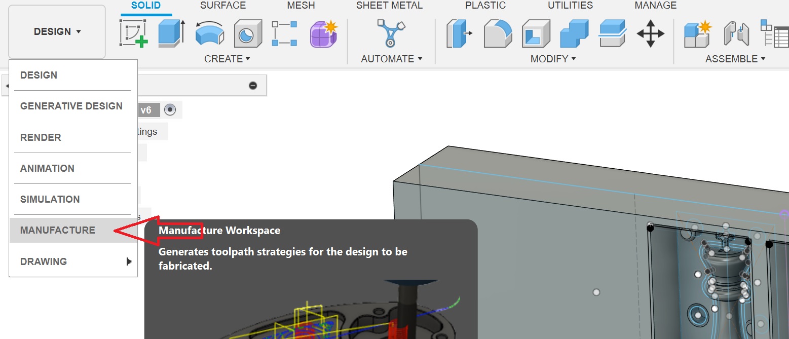
To access the Manufacturing workspace in Fusion 360, go to the dropdown menu in the Machining section and select the Manufacturing Environment option.
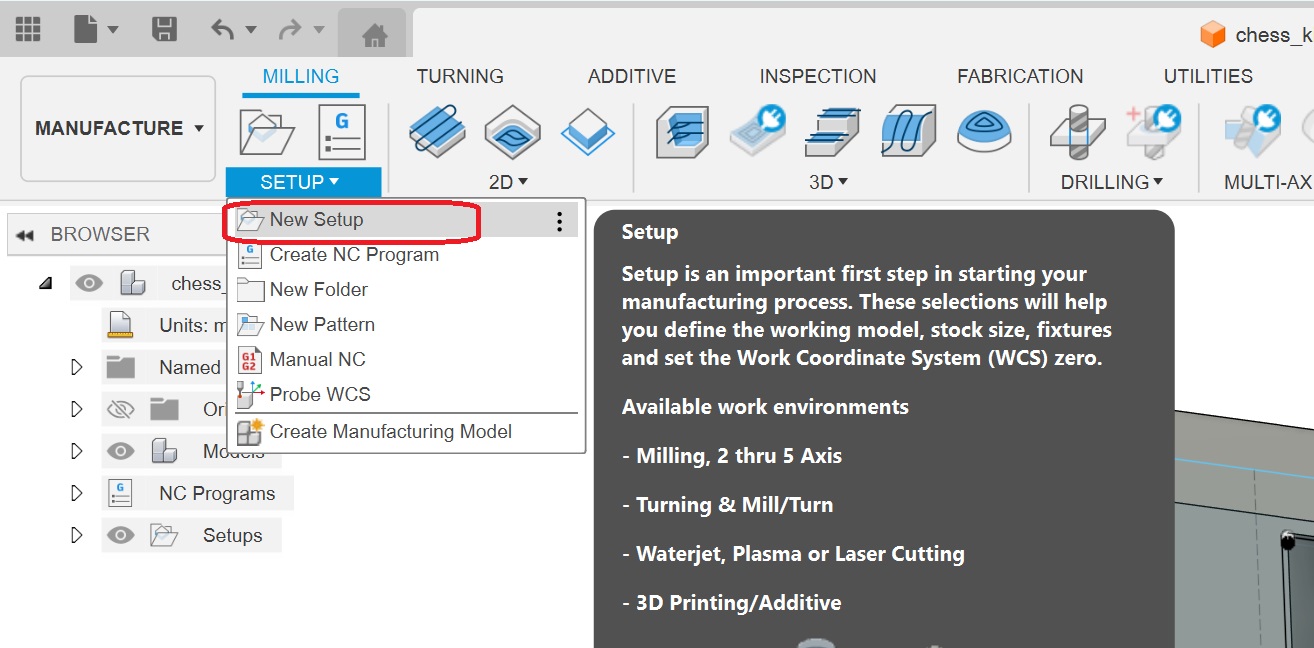
Once you're in this environment, you'll need to configure some settings. Begin by establishing the machining interface. You can do this by selecting Setup > New Setup.
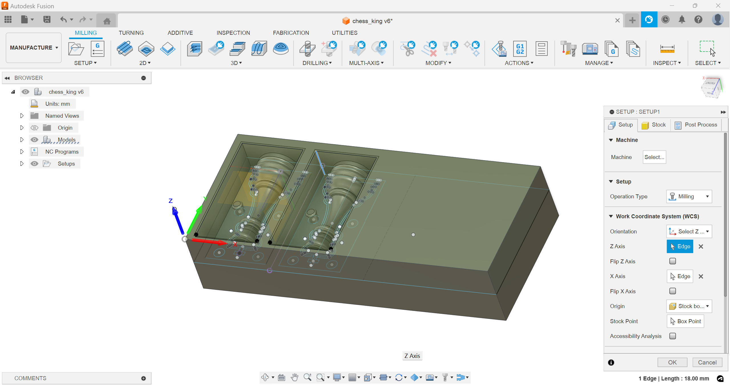
The initial task is to set the stock and axes correctly. It's crucial to set the Work Coordinate System (WCS) offset to 1.
After completing the initial setup, the next step is to select the required tools for the project. To add tools to your tool library, go to Manage > Tool Library.
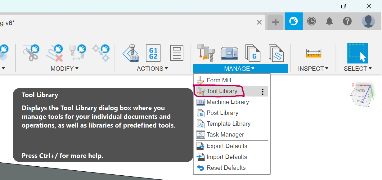
I've integrated the tool library from our FabLab, which contains all the tools currently in use. Attaching the library below here
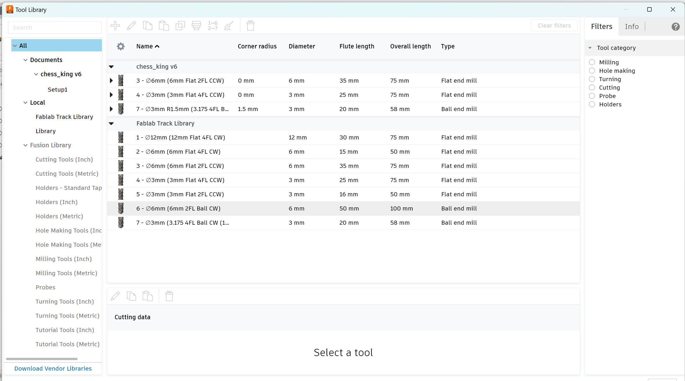
For my design milling, I opted for 4 separate operations. All of these operations can be found under the 3D section in the toolbar.
Adaptive Clearing 1:
Mill Bit: 6mm Flat End Mill 2 Flutes
Adaptive Clearing 2:
Flat:
Mill Bit: 3mm Flat End Mill 4 Flutes
Contour:
Mill Bit: 3mm Ball Nose Mill 4 Flutes
Additional Common Settings:
- Spindle Speed: 4000 rpm
- Cutting Feedrate: 900 mm/min
- Retraction Policy: Minimum Retraction
- Ramping Angle: 20 deg (for Contour: 2 deg)
Once everything was set up, the next step was to generate the G-codes. To do this, I right-clicked on the job and selected "Post Process."
Then, I specified the location where I wanted to save the G-code, chose the appropriate tools, and proceeded to export the G-code.
DPM RX2 Vertical Milling Machine
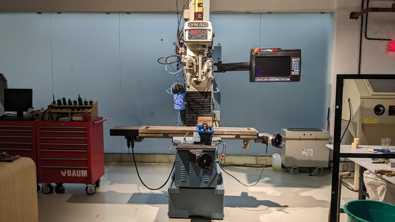
The vertical milling machine serves as a precise tool tailored for shaping and fabricating through the removal of stock, typically from metal workpieces. These operations are aimed at producing a flat surface or specific spot on a workpiece, often with a particular orientation relative to other features, surfaces, or another piece.
Specifications:
- The table size measures 1240 x 230 mm.
- Equipped with a 3 HP Continuous Spindle Motor.
- Offers axis travel of 800 x 400 x 650 mm.
- Spindle Taper: R8
- Head Swivel: +/- 90 degrees
- Quill Diameter: 33/8 inch
- Maximum Quill Travel: 5 inch
- Applications include manual and CNC milling of metals.
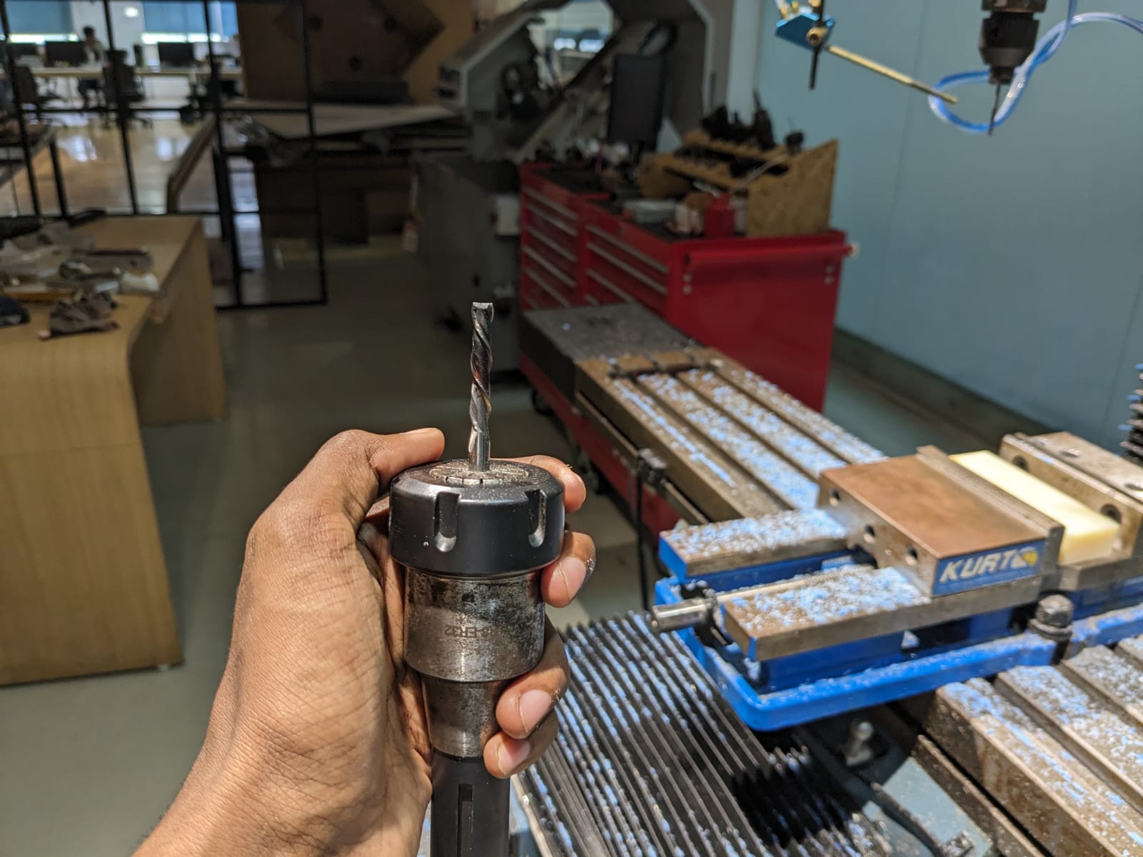
Setting up the Machine
To change the tool, we can utilize the following buttons:
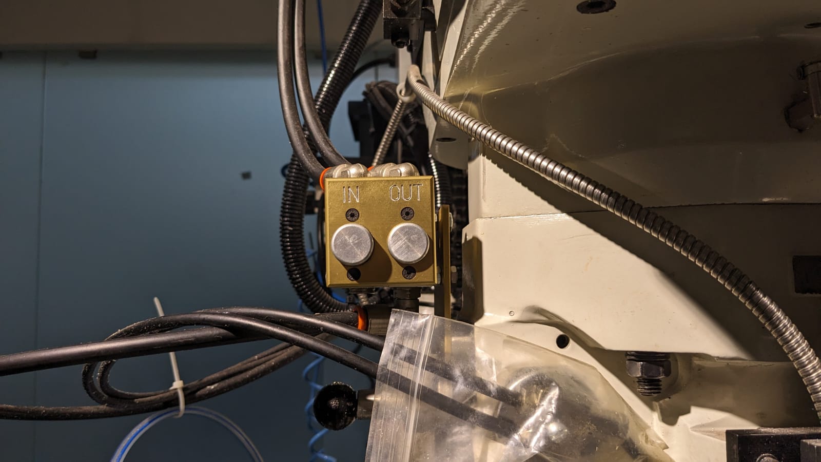
- "Out" to remove the current tool
- "In" to insert the new tool
The machine required several operations to be completed before milling the piece.
The initial step is setting the origin, which involves attaching the edge finder to the machine and establishing the tool offset.
Once the origin is set, the program can be loaded, and the tool offset adjusted for each specific tool utilized in the machining process.
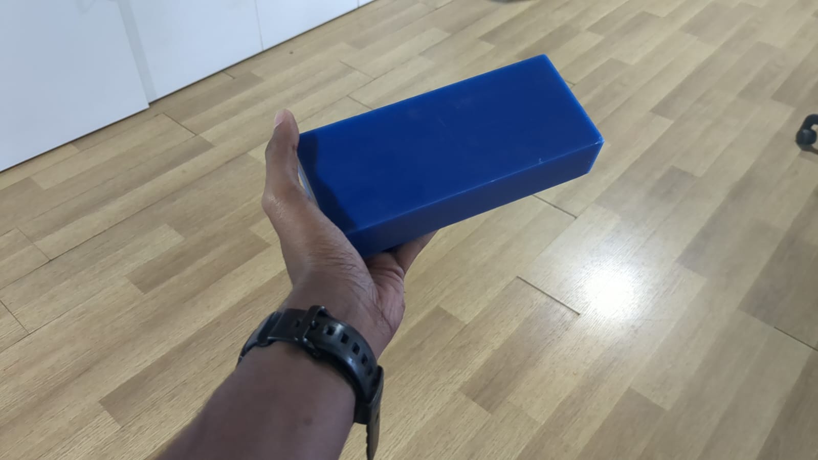
this is the stock material that i have used
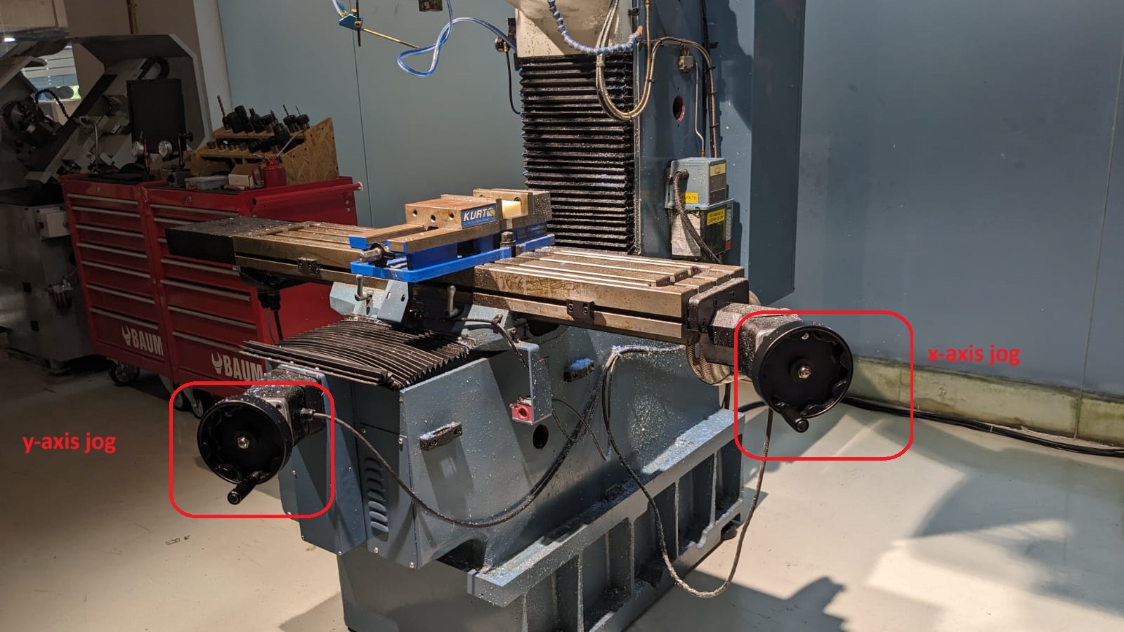
Once the material is secured, utilize the rotary encoders to adjust the X and Y axes.
Alternatively, you can use the machine interface in conjunction with an edge finder to establish the X and Y coordinates and then set the absolute X and Y axes.
Next, adjust the Z-axis by lowering the tool. After completing all adjustments, set the reference Z axis by moving the tool downward once more.
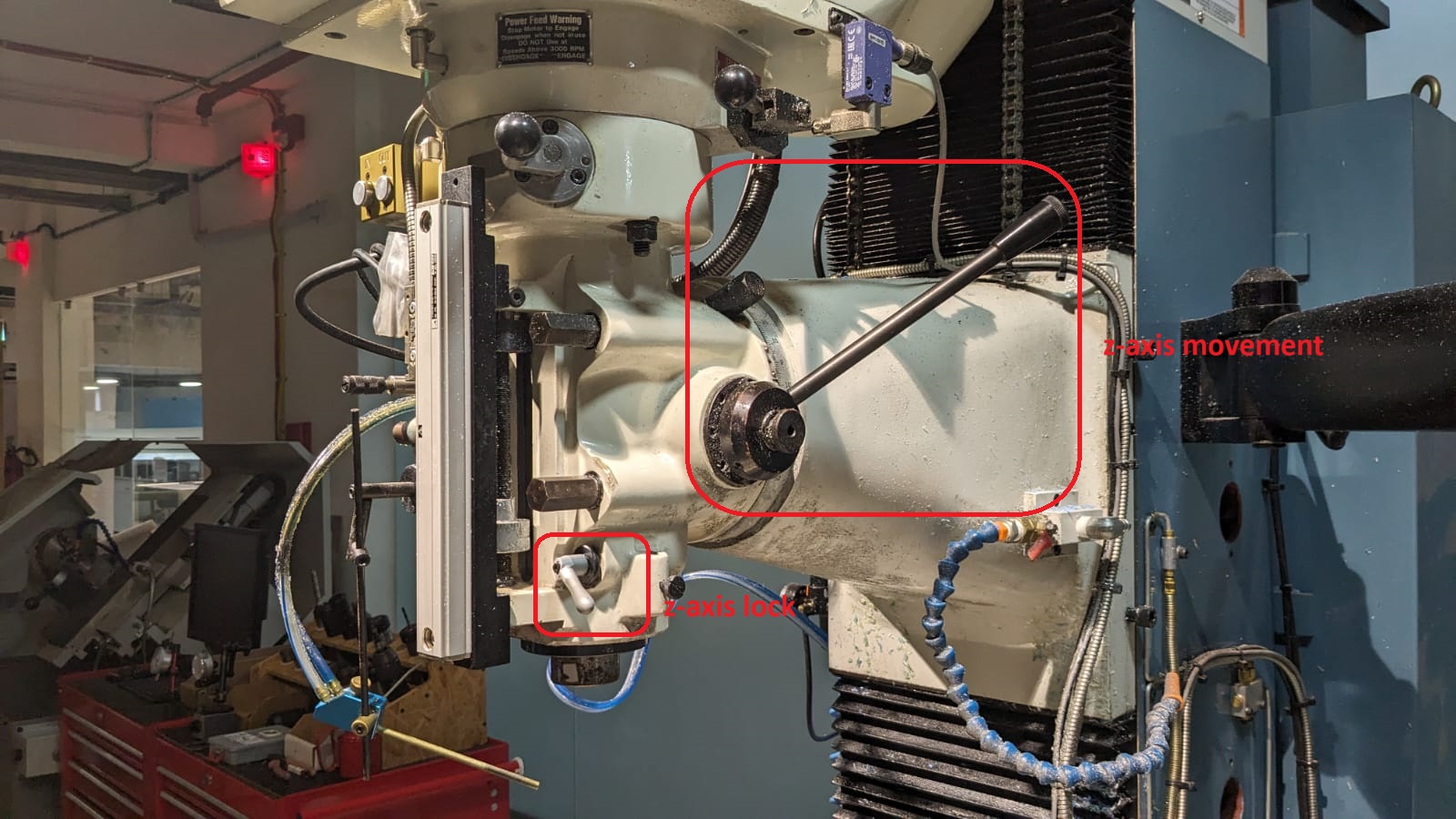
Establishing the tool reference ensures that the origin remains fixed during any subsequent tool changes.
Once the origin is established, the next step is to upload the program.
Click on "Prog In/Out" on the screen and add the file.
Then, proceed to add the tool details, such as its diameter and number of flutes, by clicking on "Tool Table".
Before directly running the codes, it's advisable to perform a "tracking" process to ensure that all the given parameters are correct and that the work is being done properly. Once satisfied with the setup, click on "CNC Run" to initiate the milling process on the machine.
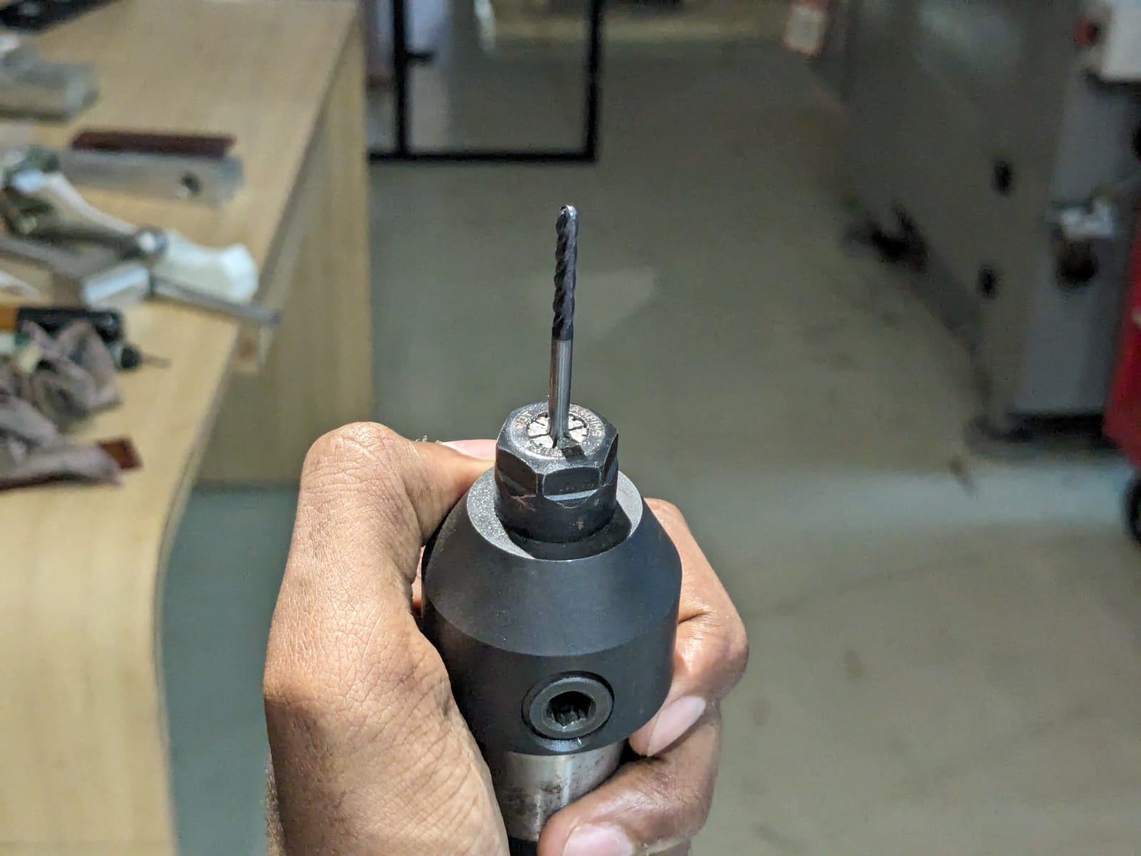
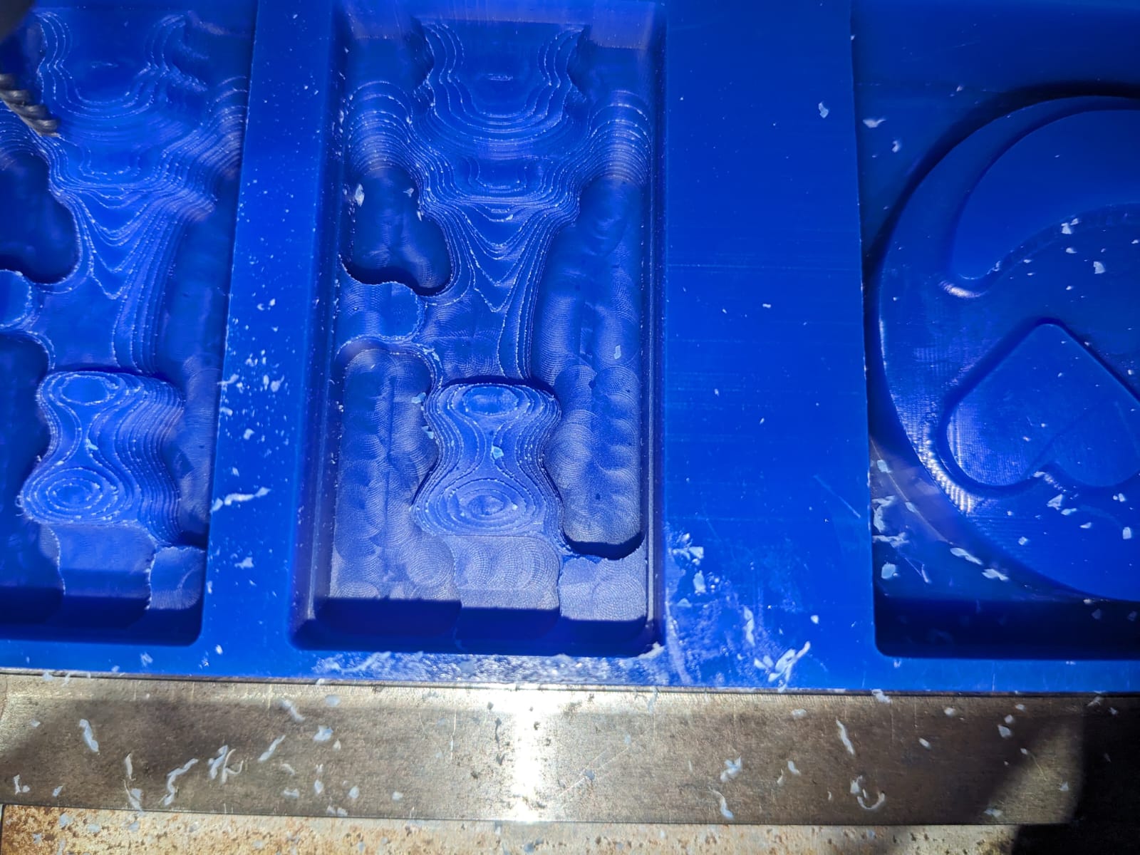
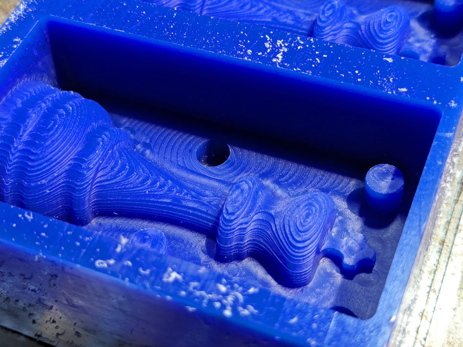
After completing the first operation, the 6mm bit has removed most of the unnecessary parts.
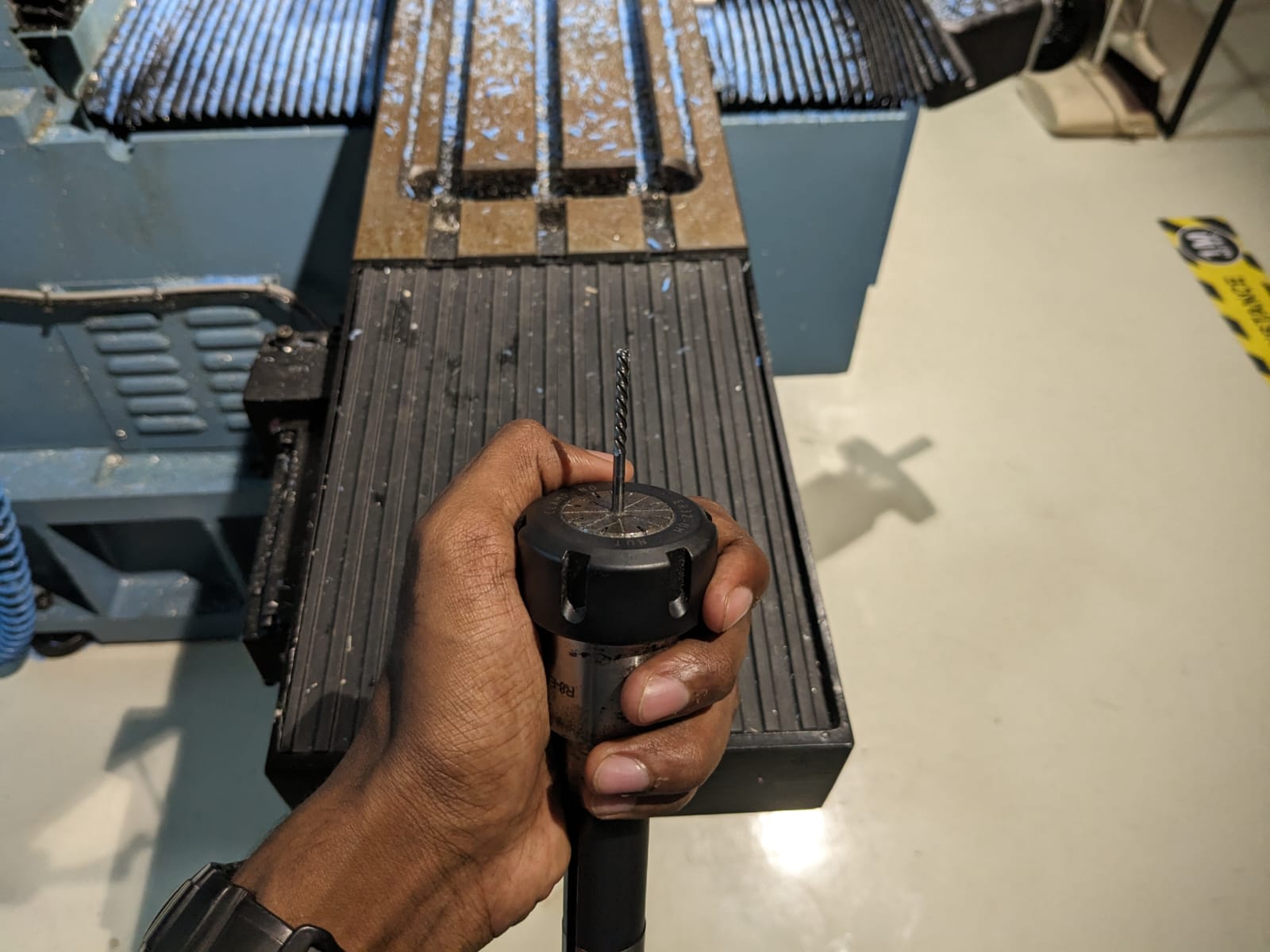
For the subsequent two operations, a 3mm flat end bit is inserted. And here is the output after using 3mm bit
Finally, for finishing touches, a 3mm ball nose bit is added. Now its looks perfect
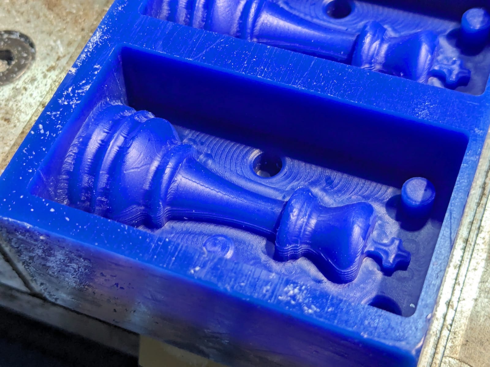
This is the final output of the milling process.
Molding
To create the mold, we utilized Silicone Rubber RTV 1010.
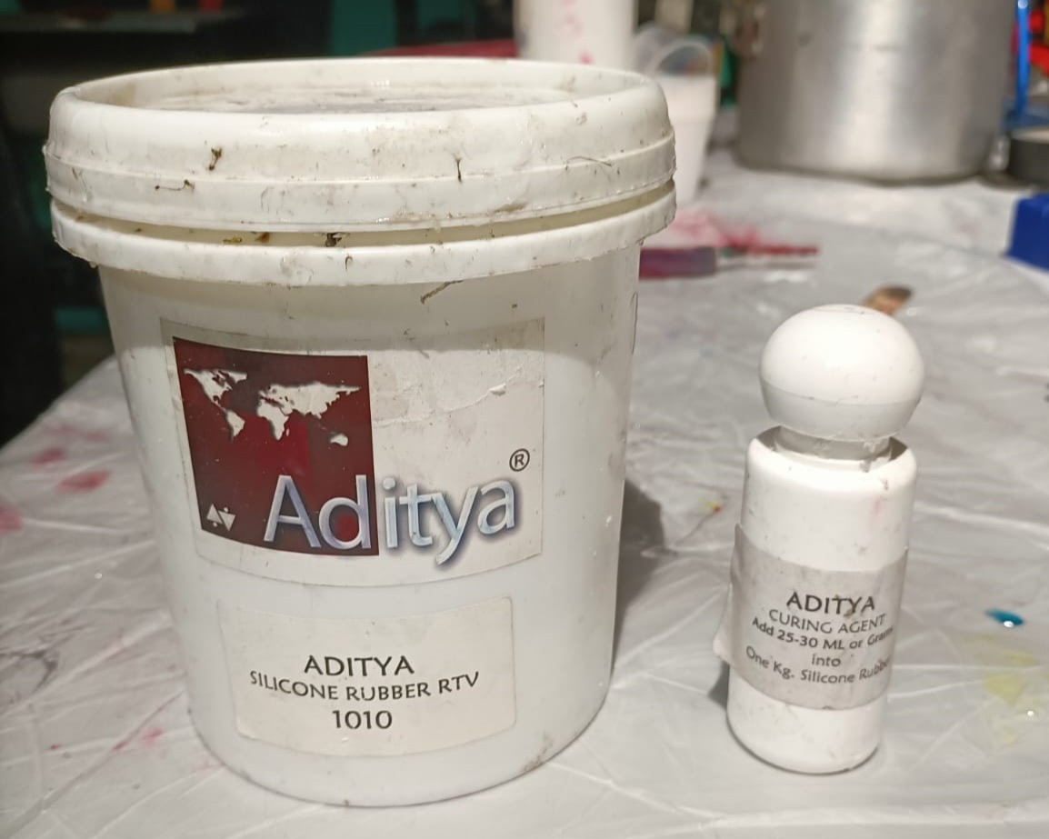
This is a dual-component silicone rubber specifically designed for mold making and prototyping purposes.
It comprises a silicone rubber base and a curing agent that need to be mixed in a precise ratio to initiate the curing process.
The mixing ratio is 10 parts silicone to 3 parts curing agent.
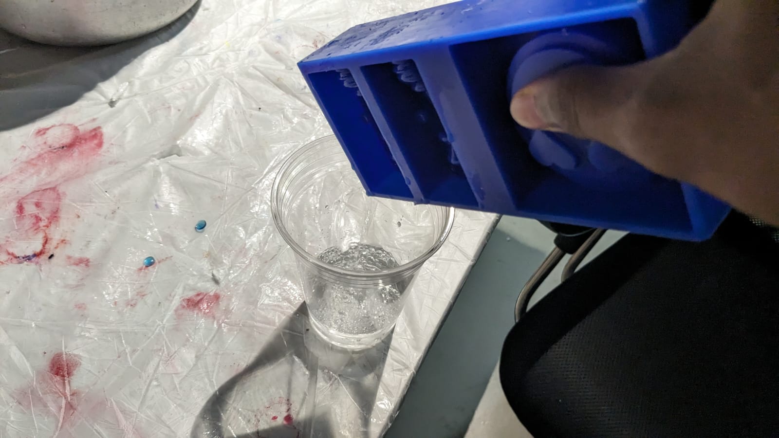
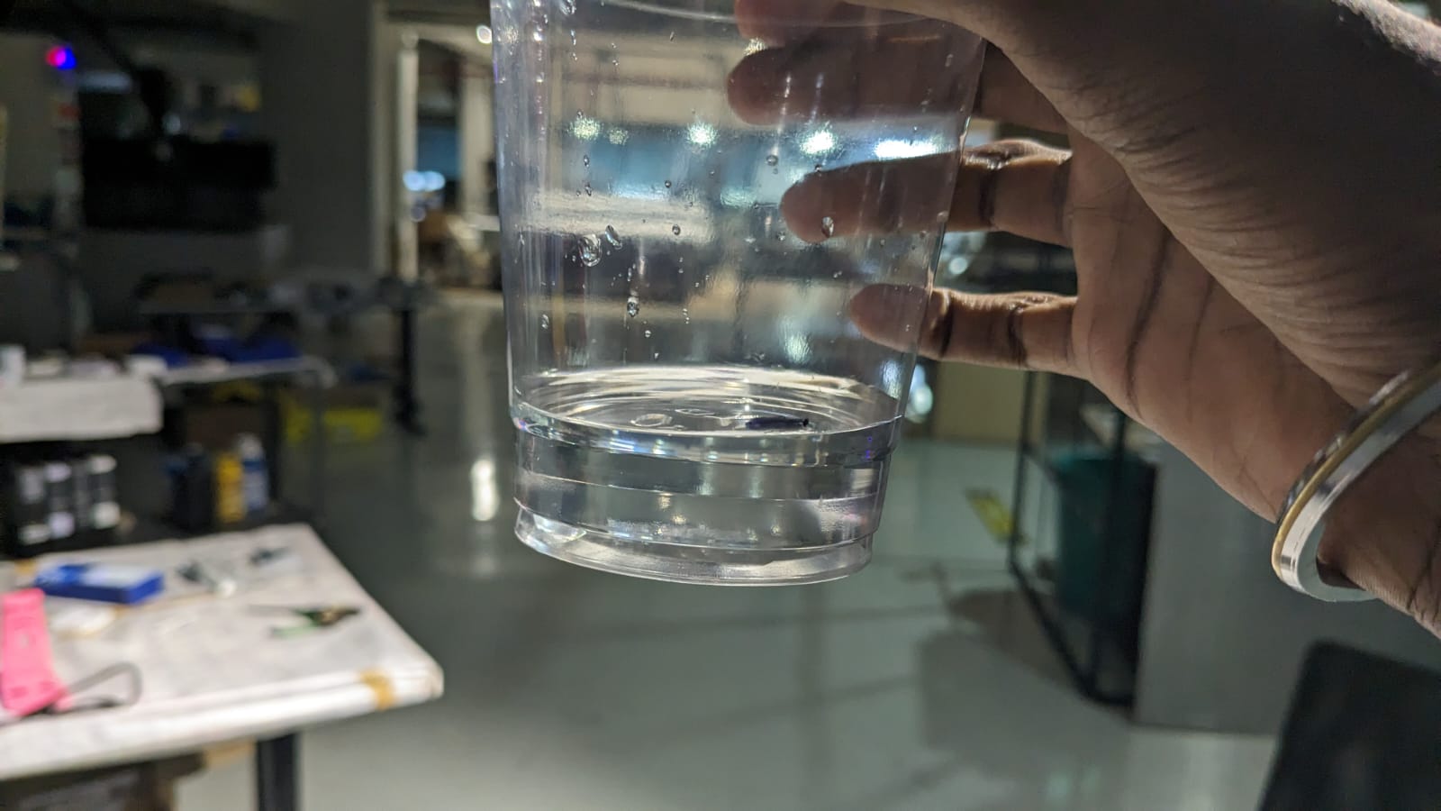
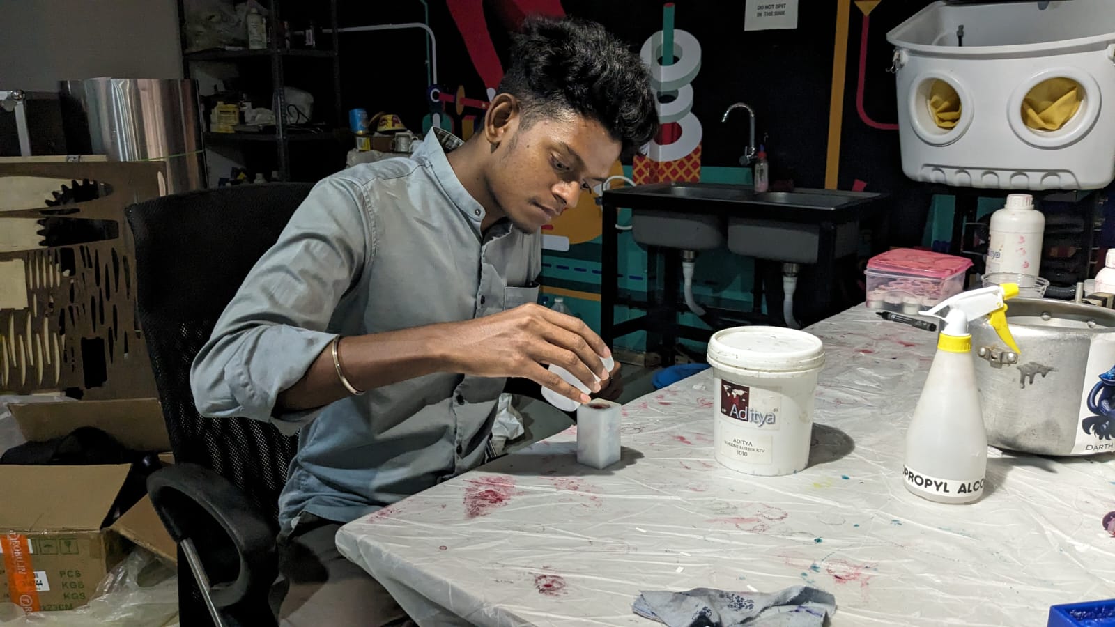
To determine the amount of silicone needed, I filled the mold with water and poured it into a glass, marking the level. This helped me understand the volume of silicone required for the mold.
After determining the correct amount of silicone needed, I mixed it with the appropriate amount of curing agent. Then, I poured the mixture into the mold and allowed it to cure for a day.
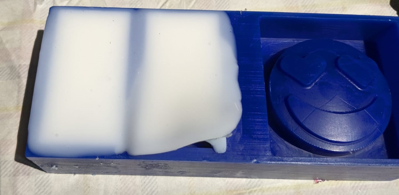
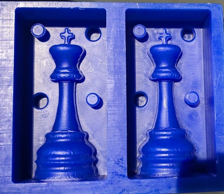
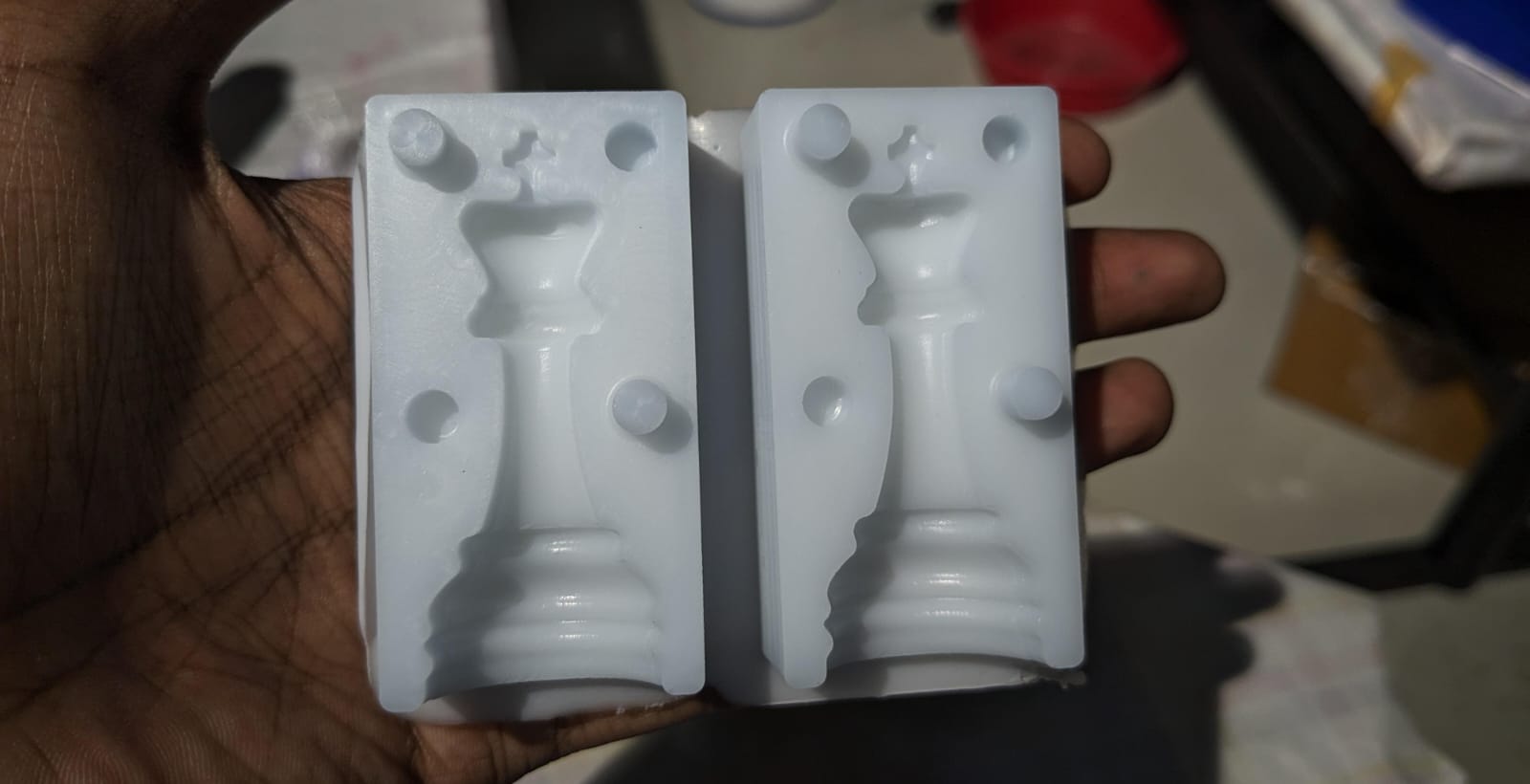
On the following day, I removed the silicone mold, and it appeared perfect, indicating successful curing. This is how it came
Casting
The final step involves pouring the resin into the cured silicone mold. Once the resin cures, the final product will be ready. For this process, we utilized Aditya Epoxy Resin 37.
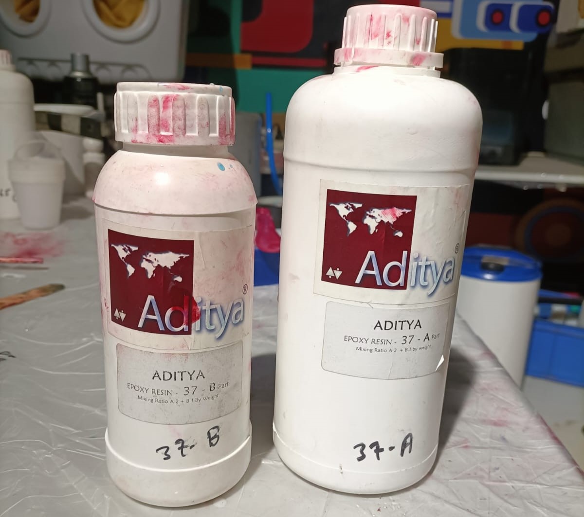
The Aditya Epoxy Resin 37 consists of two components: Part A and Part B,
Which are to be added in a ratio of 2:1.
To remove air from the resin after mixing, I utilized an in-house built vacuum chamber.
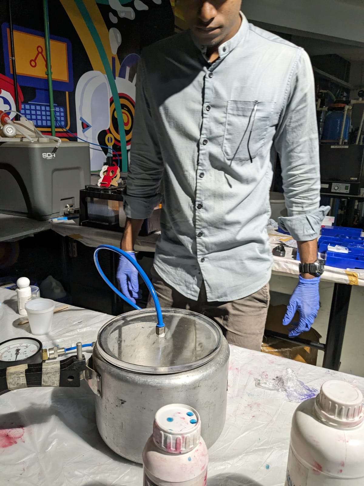
Once the air was removed, I poured the resin into the silicone mold. To enhance its appearance, I added some color and glitter to give it a cool and visually appealing look.
Just for fun, I decided to add a faulty micro SD card into the resin mixture.
I then left it to cure along with the resin.
After two days, I opened it, and here's the short video.
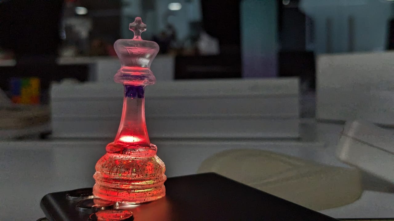
Here is the final look of the king chess piece. It looks amazing!